Color Toolkit

Background

I love color. In fact, one of my first posts I ever wrote for my developer website was based on setting up color printing for console output (which is super useful for distinguishing errors from normal informational output).

In my current code base, I have a whole library dedicated to Color. In this article, I’d like to share some code and insights for a few constructs I find really useful in everyday development.

RGB Color

Let’s start with the basics. Color32 is a simple 32-bit color structure with four 8-bit unsigned integer components: red (R), green (G), blue (B), alpha (A). Each of the components range from [0,255].

The class only has a small set of member functions for clamping, linear interpolation between two colors, etc. Also, a Color32 can be specified from four floats (range: [0,1]), though the component values are immediately converted to the byte representation.

Color-Space Conversions

RGB is so ubiquitous because it’s the color-space that rendering API calls expect for their color inputs. However, converting from RGB to other color-spaces (and back) is very important because some color operations are more natural in other color-spaces.

For the purpose of this article, we will concentrate on Hue-Saturation-Value (HSV).

HSV Color

HsvColor contains four float components: hue (H), saturation (S), value (v), alpha (A). Each of the components range from [0,1].

It is important to note that the HSV color-space is actually a cylinder, and the hue component is actually an angular value. I like to keep hue in the same [0,1] range as the other components, but that’s just a personal preference. Just be sure to convert your hue appropriately when implementing your RgbToHsv() and HsvToRgb() routines.

Furthermore, don’t be troubled that this object is a bit more heavyweight than the Color32. The main purpose for the HsvColor is to use it as a vehicle for color computation as opposed to storage.

Color Generator

Generating a good sequence of unique colors is not as trivial as it sounds. Using random number generators produces poor color sequences, and I didn’t want to limit myself to a hand-picked list of “good” colors. Instead I wanted to be able to generate a list of colors for an arbitrary size depending upon the requirements of the code. As a result, I found a couple of different articles on the subject (see References below) and implemented my own lightweight ColorGenerator class.

Internally, it uses the HSV color-space to generate a new unique color each time Generate() is called. The saturation and value components are kept constant during generation, while the hue is rotated around the HSV color cylinder using the golden ratio.

const float cInvGoldenRatio = 0.618033988749895f;

The Generate() routine below uses the cInvGoldenRatio constant as the hue increment.

Color32 Generate() const
{
   const float nextHue = mHsvColor.H + cInvGoldenRatio;
   mHsvColor.H = MathCore::Wrap(nextHue, 0.0f, 1.0f);
   return ColorOps::HsvToRgb(mHsvColor);
}

It’s important to note that the colors are not pre-generated and stored. Instead, I simply have a single HsvColor that stores the state of the generator between calls to Generate().

Color Palette

The ColorPalette class is a named container of colors. The array of colors is set on construction, and each individual color can be accessed via the bracket operator.

I call it a “palette” because it stores a fixed array of colors that are not assumed to be associated with each other in any particular way (order doesn’t matter, etc.). Although this class seems trivial, it serves as a basis for a couple really cool constructs.

Prefab Color Palettes

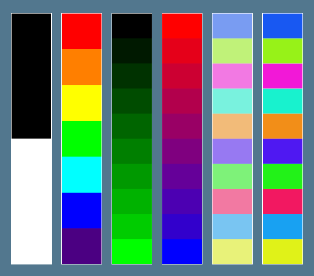
As a convenience, I have a set of ColorPalette creation routines (listed and respectively displayed in the image below).

  • Black and White.
  • Rainbow: Red, Orange, Yellow, Green, Cyan, Blue, Violet.
  • Monochrome: single color spectrum (more precisely: a spectrum from black to a single color).
  • Spectrum: a set of bands between two colors.
  • Pastels: a generated set of pastel colors. (h:0.0f, s:0.5f, v:0.95f)
  • Bolds: a generated set of saturated colors. (h:0.0f, s:0.9f, v:0.95f)

Color Ring

A ColorRing is a simple wrapper class that operates on a given ColorPalette, treating it like a circular list. Each time client code calls GetColor(), the current color is returned and the current color index is increased (wrapping back to 0 if it passes the last color).

This class useful when you have a group of items but want to limit their color choices to a certain set of colors (which may or may not be equal to the number of items): build a palette with your desired set of colors and then use a ColorRing when performing the color assignment.

Color Ramp

The ColorRamp class also operates on a given ColorPalette. It treats the ColorPalette as its own color subspace that can be accessed via a parametric value in the range of [0,1]. In other words, when client code wants a color from the ColorRamp, they must provide a parametric value which is then mapped into the ColorPalette.

Additionally, my implementation includes a RampType flag that indicates whether it will behave as a gradient or whether it will round (up or down) to the nearest neighboring color in the palette.

The Evaluate() routine uses the given parametric value to find the two nearest colors, and then computes a resulting color based on the aforementioned RampType flag. In the case of the gradient, the colors are linearly interpolated with the parametric value remainder; while the other two behaviors simply round to one color or the other based on the parametric value remainder.

Color32 Evaluate(const float parametricValue) const
{
   if (parametricValue <= 0.0f)
      return mColorPalette[0];

   if (parametricValue >= 1.0f)
      return mColorPalette[mColorPalette.Count-1];

   const float cValue = parametricValue * (mColorPalette.Count - 1);

   const int idxA = (int)MathCore::Floorf(cValue);
   const int idxB = idxA + 1;

   switch (mRampType)
   {
      case RampTypeId::eGradient:
         {
            const float fracBetween = cValue - (float)idxA;
            const Color32& colorA = mColorPalette[idxA];
            const Color32& colorB = mColorPalette[idxB];
            return Color32::Lerp(colorA, colorB, fracBetween);
         }

      case RampTypeId::eRoundDown:
         return mColorPalette[idxA];

      case RampTypeId::eRoundUp:
         return mColorPalette[idxB];

      default:
         PULSAR_ASSERT(false);
         break;
   }

   // should never get here
   return Color32::eBlack;
}

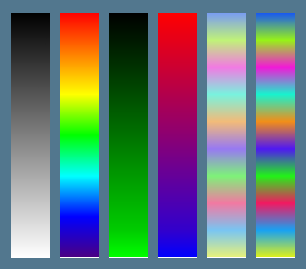
Here’s what it looks like when we create a corresponding gradient ColorRamp for each of the palettes shown above:

Initially, I wrote the ColorRamp class to help with assigning color values to vertices in a height field, but since then I have found several other interesting applications for it.

Final Thoughts

While I concentrated on exhibiting a few of the core classes in my Color library at a high level, it should be pretty clear that there are a lot of possibilities when it comes to Color. You can find more in-depth information, gritty details, and sample code in the references provided below. I highly encourage you to read them even if you’re only the slightest bit interested — they are well worth your time.

References

Unit Testing Ambiguity

Background

This post is related to the previous post on testing a return value that consists of a set of items with no predefined order (see Unit Testing Unordered Lists)[1]. However, it differs in that this time the problem is a little more mathematical in nature: how do we properly test a routine that performs an operation that may have multiple correct solutions?

For those of you who have written core math routines and solvers before, you know exactly what I’m referring to, but even if you haven’t I still encourage you to continue reading. I’ve chosen a relatively simple, common, yet important example to work through — there’s a good chance you’ll make use of this knowledge somewhere.

Unit Testing Ambiguity

There have been times when I’ve found myself trying to impose unrealistic expectations on my routines. Of course, when I test for them, I end up with failed tests and my first thought is more often than not: the code being tested must be wrong. However, the reality is that I have actually written a bad test.

A good example of this happened to me when I was working on my ComputeOrthoVectors() routine[2]. The purpose of the function is: given a single Vector3, compute two additional Vector3s which form an orthonormal basis with the input Vector3. So, I wrote the following test:

TEST(CanComputeOrthoBasisVectors)
{
   Vector3 vecA, vecB;
   ComputeOrthoBasisVectors(vecA, vecB, Vector3::UNIT_X);
   CHECK_ARRAY_CLOSE(Vector3::UNIT_Y, vecA, 3, EPSILON);
   CHECK_ARRAY_CLOSE(Vector3::UNIT_Z, vecB, 3, EPSILON);
}

The primary issue here is that the operation itself is soaked in ambiguity. More specifically, the two Vector3s that make up the return value can be produced by one of many valid solutions. To see this, let’s look at the math required for the implementation.

Computing an Orthonormal Basis

First, let’s be clear on the terminology: a set of three Vector3s that are each perpendicular to the other two is called an orthogonal basis. If we normalize the vectors in the set, we can call it an orthonormal basis. In other words: A 3D orthonormal basis is a set of three vectors that are each perpendicular to the other two and each of unit length.

The need for creating an orthonormal basis from a single vector is a fairly common operation (probably the most common usage is in constructing a camera matrix given a “look-at” vector).

Given two non-coincident[3] vectors, we can use the cross product to find a third vector that is perpendicular to both the input vectors. This is often why we say that two non-coincident vectors span a plane, because it is from these two vectors that we can compute the normal to that plane.

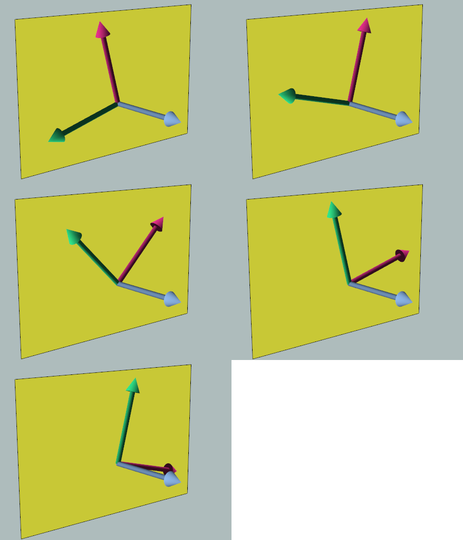
The thing to note here is that there are an infinite number of valid non-coincident vectors that span a plane. You can imagine grabbing the normal vector as if it were a rod connected to two other rods (the input vectors) and spinning it; any orientation you spin it to is a valid configuration that would produce the same normal vector. I have created an animation demonstrating this below:

Animation of two vectors orthogonal to input vector. The two vectors remain in the plane defined by the input vector (the plane normal).

In essence, this is why the results of the operation are valid, yet, for the lack of a better word, ambiguous. In the case of our routine, we are supplying the normal and computing two other vectors that span the plane. The fact that the two returned vectors are orthogonal to the input vector does not change the fact that there are an infinite number of configurations.

Testing the Geometry, Not the Values

Returning to the original testing dilemma, since there are an infinite number of possible solutions for our returned pair of Vector3s, if we write tests that check the values of those vectors, then our tests will be bound to the implementation. The result is a ticking time-bomb that may explode in our face later on (maybe during an optimization pass) because, although we may change the pair of vectors returned for a given input, the three vectors still form an orthonormal basis — the correct and desired result — in spite of the fact that we now have failing tests.

My solution was to check the following geometric properties:

  1. All three vectors are perpendicular to each other (in other words, they form an orthogonal basis).
  2. The two returned vectors are of unit length (input vector is assumed to be normalized).

The following are a few tests (straight from my codebase) that employ this approach:

TEST(CanComputeOrthoBasisVectors_UnitX)
{
   Vector3 vecA, vecB;
   ComputeOrthoBasisVectors(vecA, vecB, Vector3::UNIT_X);
   CHECK_CLOSE(0.0f, vecA.Dot(vecB), EPSILON);
   CHECK_CLOSE(0.0f, vecA.Dot(Vector3::UNIT_X), EPSILON);
   CHECK_CLOSE(0.0f, vecB.Dot(Vector3::UNIT_X), EPSILON);
   CHECK_CLOSE(1.0f, vecA.Mag(), EPSILON);
   CHECK_CLOSE(1.0f, vecB.Mag(), EPSILON);
}

TEST(CanComputeOrthoBasisVectors_UnitY)
{
   Vector3 vecA, vecB;
   ComputeOrthoBasisVectors(vecA, vecB, Vector3::UNIT_Y);
   CHECK_CLOSE(0.0f, vecA.Dot(vecB), EPSILON);
   CHECK_CLOSE(0.0f, vecA.Dot(Vector3::UNIT_Y), EPSILON);
   CHECK_CLOSE(0.0f, vecB.Dot(Vector3::UNIT_Y), EPSILON);
   CHECK_CLOSE(1.0f, vecA.Mag(), EPSILON);
   CHECK_CLOSE(1.0f, vecB.Mag(), EPSILON);
}

TEST(CanComputeOrthoBasisVectors_UnitZ)
{
   Vector3 vecA, vecB;
   ComputeOrthoBasisVectors(vecA, vecB, Vector3::UNIT_Z);
   CHECK_CLOSE(0.0f, vecA.Dot(vecB), EPSILON);
   CHECK_CLOSE(0.0f, vecA.Dot(Vector3::UNIT_Z), EPSILON);
   CHECK_CLOSE(0.0f, vecB.Dot(Vector3::UNIT_Z), EPSILON);
   CHECK_CLOSE(1.0f, vecA.Mag(), EPSILON);
   CHECK_CLOSE(1.0f, vecB.Mag(), EPSILON);
}

TEST(CanComputeOrthoBasisVectors_RefPaperExample)
{
   Vector3 vecA, vecB;
   const Vector3 unitAxis(-0.285714f, 0.857143f, 0.428571f);
   ComputeOrthoBasisVectors(vecA, vecB, unitAxis);
   CHECK_CLOSE(0.0f, vecA.Dot(vecB), EPSILON);
   CHECK_CLOSE(0.0f, vecA.Dot(unitAxis), EPSILON);
   CHECK_CLOSE(0.0f, vecB.Dot(unitAxis), EPSILON);
   CHECK_CLOSE(1.0f, vecA.Mag(), EPSILON);
   CHECK_CLOSE(1.0f, vecB.Mag(), EPSILON);
}

By testing these properties, as opposed to testing for the resulting vector values directly (as in the original test shown above), it doesn’t matter how the internals of the ComputeOrthoBasisVectors() produces the two returned Vector3s. As long as the input vector and the returned vectors all form an orthonormal basis, our tests will pass.

Final Thoughts

My hope is that the example presented in this article demonstrates one of the pitfalls of having tests that depend on the internal implementation of the routine being tested. As I have stated before, although it is important to write tests for the functionality, it can be difficult to recognize when a test is bound to the implementation.

A good place to start looking for this sort of scenario is in tests that explicitly check return values. Certainly, explicit checks is actually what you want in most cases, but for some operations it is not.

Footnotes

1. Originally, these two topics were going to be addressed in a single article, but I decided against it in hopes that keeping them separate would allow for more clarity in each.

2. In fact, the trouble I had in testing the ComputeOrthoVectors() routine is what inspired me to post both this article and the last.

3. Two vectors are said to be coincident if they have the same direction when you discard their magnitudes. In other words, two vectors are coincident if you normalize both of them and the results are the same.

References

Möller, Tomas and John F. Hughes. Building an Orthonormal Basis from a Unit Vector. [ pdf ]

Unit Testing Unordered Lists

Background

If you’ve read just about any of my earlier posts, you know that I write tests for Pulsar. This includes unit tests, functional tests, and performance tests, all in addition to the demo / visual tester applications that I usually post my screenshots from. The details on the structure to my codebase are probably worth outlining in a future post, but in this post now I’m going to focus in on the unit tests.

Implementation Note: I use UnitTest++ as my test harness. It is simple, lightweight, and quick to integrate into a codebase. If you don’t have a testing framework setup for your codebase yet, I highly recommend UnitTest++.

Unit Testing Unordered Lists

Every once in a while (primarily in my Geometry / Collision Detection library), I have run into the need for unordered lists in my test suite. In fact, it has come up often enough that I decided to share some thoughts and my solution here.

Although I’m going to explain this issue through a somewhat contrived example, I chose it because the premise is easy to understand and visualize; certainly this could be extended to other, more complex cases.

Let’s say you have the following Rectangle class that represents an 2D axis-aligned box:

class Rectangle
{
public:
   Vector2 mMin;
   Vector2 mMax;
};

Next, say we are writing a ComputeCorners() member function. As you probably guessed, this routine needs to return four Vector2s that are the coordinates of each of the corners on the Rectangle. This can be done in one of the following two flavors:

  • add a struct with four Vector2s, each with sensible member names
  • use an array: Vector2[4]

If your calling code requires explicit knowledge that maps each returned point to its corresponding corner on the Rectangle, you would probably choose to use the first option.

However, let’s assume that all we actually need are the points themselves and we don’t really care which point is which (maybe we’re just going to insert them into some larger list of points that will be processed, or whatever). Using the array approach, our test code might look something like this:

TEST(CanComputeCorners)
{
   Rectangle rect;
   rect.mMin.Set(1.2f, 1.4f);
   rect.mMax.Set(2.5f, 1.7f);
  
   Vector2 corners[4];
   rect.ComputeCorners(corners);
  
   CHECK_EQUAL(Vector2(1.2f, 1.4f), corners[0]);
   CHECK_EQUAL(Vector2(2.5f, 1.4f), corners[1]);
   CHECK_EQUAL(Vector2(1.2f, 1.7f), corners[2]);
   CHECK_EQUAL(Vector2(2.5f, 1.7f), corners[3]);
}

Without sweating the details of testing against an epsilon, this test looks pretty good at first glance, and it probably succeeds without trouble.

However, there is a subtle problem here: our test is assuming that there is a specific order to the points being returned. Nothing in our function dictates that we absolutely have to return the points in that order, but because of the way we have written our test any change to the order of the returned points in the implementation will result in a failing test.

So how exactly can we test this routine (and others like it) properly? In other words, how can we write our test to be order-independent?

My solution (as straightforward as it may be) was to implement a testing helper routine:

bool ArrayContainsItem(
   const Vector2* itemArray, const uint itemCount,
   const Vector2& itemToFind)
{
   for(uint idx = 0; idx < itemCount; ++idx)
   {
      const Vector2& curItem = itemArray[idx];
      if(curItem == itemToFind)
         return true;
   }
  
   return false;
}

TEST(CanComputeCorners)
{
   Rectangle rect;
   rect.mMin.Set(1.2f, 1.4f);
   rect.mMax.Set(2.5f, 1.7f);
  
   Vector2 corners[4];
   rect.ComputeCorners(corners);
  
   CHECK(ArrayContainsItem(corners, 4, Vector2(1.2f, 1.4f));
   CHECK(ArrayContainsItem(corners, 4, Vector2(2.5f, 1.4f));
   CHECK(ArrayContainsItem(corners, 4, Vector2(1.2f, 1.7f));
   CHECK(ArrayContainsItem(corners, 4, Vector2(2.5f, 1.7f));
}

Notice that this routine is intended for the purposes of simplifying the test and resides with the testing code, not packaged up with the library itself. It is perfectly acceptable to have to perform additional setup (mock objects, etc.) or implement a helper or two for testing.

Also, you could certainly generalize this unit test helper routine a little so it can be used in other unordered list instances -- I've found many uses for my own implementation while testing Pulsar libraries.

Final Thoughts

The real take away from this actually isn't about how to test an unordered set of objects; in fact, I think the lesson is much bigger and important: be careful to write tests for the functionality, not for the implementation.

This key point to this lesson is subtle and sometimes easy to miss / hard to catch.

To be clear, functionality is what the routine does that can be inspected from the outside view of the object, or, in the case of a non-member ("free") function, from the return value. On the other hand, implementation is much more tightly bound to the code itself (the internal process of a routine) and how it operates on an object or data.

In the example case above, we saw that the interface did not specify an ordering for the list of returned corner coordinates, yet our initial test definitively expected an ordering which happened to be based on our knowledge of the implementation.

I'll be the first to admit that it isn't always clear when implementation details have crept into the tests -- this has happened to me a lot more often than I care to reveal (especially while practicing Test-Driven Development).

In closing, I believe that the first line of defense against this problem is to simply be aware that it can show up when testing container return values. As a result, I encourage you to take some additional time to make sure that the tests really are testing the functionality and not the implementation.

Book Review: Software Engineering for Game Developers

Software Engineering for Game Developers

Software Engineering
and Game Developers

John P Flynt, Ph.D.

Thoughts Overall:

SEGD is a detailed post-mortem of a small team’s game project: Ankh. It focuses in on the process of developing a game from start to finish… with a heavy emphasis on the process. The book spans 800+ pages, many of which are tabular explanations of forms and documents. In other words — this book has “academic” written all over it. Okay, granted the Ph.D. at the end of the author’s name also indicates this fact, but I was willing to give the book a chance (as I am with a lot of books!).

Overall, I felt let down about a hundred pages into the book and it never recovered. Initially, I had high hopes because I like reading post-mortems from game projects (even if it may have been from a game that no one’s ever heard of) and I like process. However, SEGD takes its readers down a road that veers strongly towards the managerial side of game development, sans a couple of chapter sections sprinkled with the code of a few classes in an attempt to catch the attention of software engineers. Don’t get me wrong, I don’t mind reading about practices and methodologies — I grew up on SCRUM and Test-Driven Development, but there’s something wrong when a book is detailing forms from the ISO standard.

Yes, I read all of it. The best parts were when they explained the expectations they had, the methods they used, the overall outline of their setup, the roles that team members had, and the problems they ran into and how they resolved them. These were great discussions. In fact, I think the “Stripe” (iteration) methodology used is a pretty viable structure. But all this could have been wrapped up well before hitting the 500 page mark.

Do I Recommend this Book?

For this particular book, I need to you to answer my question first: Do you like digging for your information?

This book is dense and is, in fact, rewarding on varying levels for both managers and members of a game development team, but you’ll have to dig through layers of mechanics for those nuggets.

Pros:

I really appreciated the effort that went into tracking the info during the Ankh project. In fact, this is exactly why I bought the book: to read about a team project that goes from design doc to a fully functional game. It was very interesting to read about how a bunch of ideas were turned into something tangible and fun.

This book has a lot to offer in terms of how a team formulates a game and gets their ideas implemented from the initial scribblings they wrote weeks/months before. It examines an iterative development methodology (each iteration they call a “Stripe”). Each stripe is actually a complete demo that fulfills a certain set of specified requirements, along the way to the final stripe with completes the game. The book takes the reader through each stripe (not in detail for all 17, but that’s okay — it started to become monotonous after a while), and explains many important issues that arose and addresses the team dynamics.

Furthermore, each stripe is outlined (with requirements and use cases), implemented, and tested. All of these steps are elaborated upon with good context, though there is a heavy emphasis on the outlining and documentation and less so on the actual implementation.

As you might have expected, the topic of design patterns surfaces throughout the discussion. Although I had feared for the worst when I reached this chapter (due to the overall view being so lofty it made me feel uncomfortably distant from the software), it actually turned out to be one of the best chapters of the book. For SEGD, patterns wasn’t the be-all end-all I have been reading about in other sources. The chapter takes a very practical point of view and after you have finished reading it, you don’t feel like the world can be solved by patterns, rather that they are proven, structured designs to solve a distinct class of problems. This tone and treatment was very refreshing.

Cons:

After finishing this book I felt like I needed to have a formal review before moving on to the next book in my queue. My biggest complaint is the book was too focused on formalities of the game development process. I kept asking myself, “How did these guys make any progress with all these documents and meetings?”

Can I think of anything more boring to read about than metrics? I know: tables of ISO standard forms! Why the author could not have merely suggested the reader to take a look at a few forms to use as templates when setting up their design document or other related documents, rather than include pages upon pages of tables with explanations of each section (some of which boil down to “you probably don’t need to include this section”) I cannot fathom.

Don’t expect code. Classes, their objects, and the messages/events passed between them are all examined at a high architectural level. I was thinking this book might have explained more about library modules to form a game engine, but the game project itself was quite tiny in comparison to what I had already been exposed to at work, and did not discuss engine architecture to any detail. Instead, the focus was on using UML and SmartDraw to design every class in your game. Personally, I believe if you have enough foresight and patience to draw out the UML and maintain it throughout the life of a game project, you should take a step back and consider how much time you’re spending not implementing your game. Tools and documentation are there to help you convey ideas and save time — not become a ball-and-chain!

Final Word:

This was an interesting read — though I had higher hopes. The cursory content of the vast number of subjects could have been thinned and left to the reader to investigate by reading authoritative, dedicated books on the subjects. The core of the book was really the Ankh project and the Stripes methodology, but it was often times buried under too many layers of formalization. Don’t pick up this book unless you’re willing to spend a lot of time sifting through those layers.

Reading PNG Images from Memory

As far as I can tell most everyone is interested in reading PNG image data from file (internally done in libpng via fread()). I thought: “Wow, that’s quite unfortunate.” and figured I’d write about it after I figured it out. The article below is the result.

NOTE: the intent of this article is to help you get something up and running quickly. By design, it does not provide detailed explanations about the functions or interface of libpng — that’s what the documentation is for.

Motivation

There are several reasons why one might want to have data read from memory rather than directly from a file.

Testing – This was the first reason that came to my mind. In the Pulsar engine codebase, I want to test my format data loaders, which includes anything from textures and models to config files and scripts. More on this later.

Archives – If you pack a “file” into a custom archive, do you expect you want to hand a third-party library your file pointer? …

IO Performance – File IO has never been instant, and it can be worse depending upon the platform. As a result, you’re usually better off if you read in a file in its entirety as opposed to only reading a small chunk at a time, since the device may have seeked to somewhere else in between your reads.

Scenario in Pulsar

I have abstracted the operation of reading into an InputStream interface so that the source of the data (file, buffer in memory, network, or whatever) can be swapped out without affecting the behavior of the loader classes.

The function signature looks like this:

size_t InputStream::Read(byte* dest, const size_t byteCount);

You will see this used as the main data pipe in the next section.

Implementation

I will assume you have already set the include and library dependencies for libpng. The libpng documentation is pretty clear about this topic, so I won’t delve into it here.

I should also note that the code provided below is practical and is taken from a module in my codebase. It includes a basic amount of error checking, but I stripped the rest of it out for clarity sake. As such, I recommend that you use this as a starting point.

You will undoubtedly have to switch out the calls to pulsar::InputStream::Read() and replace with them your own data source’s read interface.

Lastly, I have typedefed a few basic data types in my engine. For example: byte is typedefed as an unsigned char.

Setup

First, we check if the data has the PNG signature, which is held in the first 8 bytes of the image data. If libpng determines that the signature is invalid, we bail.

enum {kPngSignatureLength = 8};
byte pngSignature[kPngSignatureLength];

// call to pulsar::InputStream::Read()
// -> replace with your own data source's read interface
inputStream.Read(pngSignature, kPngSignatureLength);

if(!png_check_sig(pngSignature, kPngSignatureLength))
   return false;

Next, we need to create a pair of file info structures. For future compatibility reasons, libpng must allocate and free the memory for these structures. If either one of these calls fail, we perform the necessary cleanup and bail.

// get PNG file info struct (memory is allocated by libpng)
png_structp png_ptr = NULL;
png_ptr = png_create_read_struct(PNG_LIBPNG_VER_STRING, NULL, NULL, NULL);

if(png_ptr == NULL)
   return false;

// get PNG image data info struct (memory is allocated by libpng)
png_infop info_ptr = NULL;
info_ptr = png_create_info_struct(png_ptr);

if(info_ptr == NULL)
{
   // libpng must free file info struct memory before we bail
   png_destroy_read_struct(&png_ptr, NULL, NULL);
   return false;
}

This is where the magic happens. Now we must tell libpng to use a our own custom routine for retrieving the image data. To do this, we use the png_set_read_fn() routine:

png_set_read_fn(png_ptr, &inputStream, ReadDataFromInputStream);

The first parameter is the pointer to the first struct we asked libpng to create for us: png_ptr.

The second parameter is a void pointer to the data source object. In this case, the data source my InputStream object.

The final parameter is a pointer to a function that will handle copying the data from the data source object into a given byte buffer. Here, my reader function is called ReadDataFromInputStream(). This routine must have the following function signature:

void ReadDataFromInputStream(png_structp png_ptr, png_bytep outBytes,
   png_size_t byteCountToRead);

Now that we have told libpng where to go when it needs to read bytes, we need to implement that routine. Mine looks like this:

void ReadDataFromInputStream(png_structp png_ptr, png_bytep outBytes,
   png_size_t byteCountToRead)
{
   png_voidp io_ptr = png_get_io_ptr(png_ptr);
   if(io_ptr == NULL)
      return;   // add custom error handling here

   // using pulsar::InputStream
   // -> replace with your own data source interface
   InputStream& inputStream = *(InputStream*)io_ptr;
   const size_t bytesRead = inputStream.Read(
      (byte*)outBytes,
      (size_t)byteCountToRead);

   if((png_size_t)bytesRead != byteCount)
      return;   // add custom error handling here

}  // end ReadDataFromInputStream()

The last piece of setup we need to do is tell libpng that we have already read the first 8 bytes when we checked the signature at the beginning.

// tell libpng we already read the signature
png_set_sig_bytes(png_ptr, kPngSignatureLength);

PNG Header

Now we are ready to read the PNG header info from the data stream. There is a lot of data one could extract from this, but here I’m only going to grab a few important values. Refer to the libpng documentation for more details on this function.

png_read_info(png_ptr, info_ptr);

png_uint_32 width = 0;
png_uint_32 height = 0;
int bitDepth = 0;
int colorType = -1;
png_uint_32 retval = png_get_IHDR(png_ptr, info_ptr,
   &width,
   &height,
   &bitDepth,
   &colorType,
   NULL, NULL, NULL);

if(retval != 1)
   return false;	// add error handling and cleanup

The width and height parameters are the image dimensions in pixels.

The bitDepth is the number of bits per channel. It is important to note that this is not per pixel (which is what is normally the value stored in a TGA or BMP).

The final parameter we care about is colorType which is an integer that maps to one of the predefined values in libpng that describe the image data (RGB, RGBA, etc). You will need this to determine how many channels you need to read from the bytes into your pixel color.

PNG Image Data

We have reached the point where we can now read in the image data into our internal image pixels.

outImage.Init(width, height);

switch(colorType)
{
   case PNG_COLOR_TYPE_RGB:
      ParseRGB(outImage, png_ptr, info_ptr);
      break;

   case PNG_COLOR_TYPE_RGB_ALPHA:
      ParseRGBA(outImage, png_ptr, info_ptr);
      break;

   default:
      PULSAR_ASSERT_MSG(false, "Invalid PNG ColorType enum value given.\n");
      png_destroy_read_struct(&png_ptr, &info_ptr, NULL);
      return false;
}

First, I initialize my internal image format, which allocates the appropriate memory for the pixels — each of which is a Color32 (red,green,blue,alpha).

The switch is to differentiate my parsing routines (one of which is listed below) based on the colorType value we retrieved from the header.

To parse the data into pixel colors all we have to do is grab each row from the image and proceed to read each tuple of bytes that represents a pixel. The number of bytes we read is dependent upon the data stored, which is why we differentiate between parsing a 24-bit (RGB) color value and a 32-bit (RGBA) color value via colorType.

I have provided the ParseRGBA() routine below. The ParseRGB() is very similar except no bytes are read for the alpha channel.

void ParseRGBA(Image& outImage, const png_structp& png_ptr,
   const png_infop& info_ptr)
{
   const u32 width = outImage.GetWidth();
   const u32 height = outImage.GetHeight();

   const png_uint_32 bytesPerRow = png_get_rowbytes(png_ptr, info_ptr);
   byte* rowData = new byte[bytesPerRow];

   // read single row at a time
   for(u32 rowIdx = 0; rowIdx < height; ++rowIdx)
   {
      png_read_row(png_ptr, (png_bytep)rowData, NULL);

      const u32 rowOffset = rowIdx * width;

      u32 byteIndex = 0;
      for(u32 colIdx = 0; colIdx < width; ++colIdx)
      {
         const u8 red   = rowData[byteIndex++];
         const u8 green = rowData[byteIndex++];
         const u8 blue  = rowData[byteIndex++];
         const u8 alpha = rowData[byteIndex++];

         const u32 targetPixelIndex = rowOffset + colIdx;
         outImage.SetPixel(targetPixelIndex, Color32(red, green, blue, alpha));
      }
      PULSAR_ASSERT(byteIndex == bytesPerRow);
   }

   delete [] rowData;

}  // end ParseRGBA()

Cleanup

Finally, now that the image data has been read we should clean up the libpng structures, then we can be on our merry way!

png_destroy_read_struct(&png_ptr, &info_ptr, NULL);

That's it! Now we can go do whatever we need to with the image data we just read in!

Conclusion

Here I've only touched on the basics. This seemingly simple task was practically nowhere to be found when I searched for it, resulting in me having to piece it together. Hopefully this will same someone else some time.

Resources